
A Hilti white paper
1. INTRODUCTION
1.1 Construction
Ungrouted stand-off connections are almost exclusively leveled using nuts below the steel plate. Castin-place or post-installed anchors are first installed in the concrete. Post-installed mechanical anchors that rely on torquing or displacement to complete anchor installation generally must first be clamped to the concrete surface at the appropriate torque/displacement.
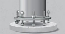
Leveling nuts and their accompanying washers are threaded and placed onto the rod roughly to the location of where the base plate will need to sit, as shown in Figure 1. The steel member is then seated onto the leveling nuts and washers, most often with assistance from a crane, and the location of the leveling nuts are adjusted to meet the proper member plumbness and other geometric requirements.
After the steel member is appropriately leveled, top nuts and washers are placed onto the plate and the nuts are tightened, such as by using the turn-of-the-nut method. Examples of an ungrouted stand-off connection during seating and in service are shown in Figure 1.
Figure 1. Ungrouted stand-off connection: during seating on leveling nuts (left) and in service (right)
1.2 Structural behavior
1.2.1 Steel resistance of anchors in ungrouted connections
Steel resistance of anchors in ungrouted connections is a function of the combination of shear, bending, and normal force acting on the exposed portion of the anchor. Figure 2 shows the load path of a wind load acting on a sign held by a mast arm through to the concrete in an ungrouted stand-off connection, from the global loads traveling to the connection (left), to the transfer of connection-level forces into individual anchor forces (middle), to the transfer of individual anchor forces through the exposed portion of an anchor through shear, axial, and bending moment forces (right).
Figure 2. Loads acting on a base connection (left), force transfer to anchors in ungrouted stand-off connections (middle; plan and profile views shown), and forces acting on exposed portion of anchor (right; double curvature shown)
Depending on the boundary conditions, anchors may either be in single or double curvature as illustrated in Figure 3. Double curvature (𝛼𝑀 = 2.0) may be assumed when the steel plate is restrained from rotation (generally by other anchors in the connection resisting the rotation), the plate is thick enough to restrain the bending moments at the plate level, and there is a rigid connection between the anchor and the plate (e.g., via clamped leveling and top nuts and/or welds). Where these conditions cannot be confidently met, single curvature (𝛼𝑀 = 1.0) should be assumed or further analysis should be performed to determine the correct value of 𝛼𝑀 between 1.0 and 2.0.
Figure 3. Anchor in single curvature (left) and double curvature (right)
McBride [3] found that the interaction between shear force, normal force, and bending moment in ungrouted stand-off connections can be expressed as described in Sections 2.2.2 and 2.2.4, which ultimately is a reorganisation of a three-way interaction equation given in McBride [3]. For anchors in combined tension and shear, the interaction equation in Eq. (1) is conservative, as it ignores beneficial second-order effects where the tensile force relieves the bending moment by acting on the displaced shape in shear. However, because nearly all anchor groups will have combinations of anchors in tension and compression, it is realistic to ignore the beneficial second-order effects on the anchors in tension.

In addition, McBride [3] verified that it is appropriate to consider bending between an assumed spall depth (generally taken as 0.5 anchor diameters) below the concrete surface to the bottom of the leveling nut. This is because the predominating curvature in an ungrouted stand-off connection occurs in the exposed portion of the threaded rod due to the high ratios of relative bending stiffness of the nut and the steel plate.
1.2.2 Concrete resistance of anchors in stand-off connections
Concrete breakout resistance in tension is assumed to be unaffected in stand-off conditions.
Concrete edge breakout forces in shear, however, may be amplified by the displacement of the anchor and additional moment traveling through the connection. Figure 4 illustrates the bending moment that acts on the concrete edge breakout body in an ungrouted stand-off anchor. This bending moment adds to the bearing pressure due to shear on the concrete and must be accounted for to properly describe behavior. Appendix A provides the basis for the factor presented in Section 2.3.2.
Figure 4. Forces acting on exposed portion of anchor (double curvature shown)
2. DESIGN METHODS
2.1 General
2.1.1 Comparison between EN 1992-4 and Hilti Method
Hilti PROFIS Engineering offers two solutions for the design of anchors in ungrouted stand-off connections: design compliant with Eurocode EN 1992-4 [1] and the Hilti Solutions for Fastenings (SOFA) Method.
EN 1992-4 design of anchors in ungrouted stand-off connections makes conservative assumptions about the lever arm for bending, the interaction between shear and normal forces, and the bending resistance of the anchor section. The Hilti SOFA Method provides a less conservative design approach while also offering a more complete solution than EN 1992-4. The Hilti SOFA Method is recommended in cases where EN 1992-4 does not provide a viable solution.
The primary differences between Eurocode design in accordance with EN 1992-4 [1] design and Hilti SOFA Method are as follows:

The Hilti SOFA Method is based on recommendations by McBride [3] that are planned for future incorporation into fib Bulletin 58, EN 1992-4, ACI 318, and other relevant anchor design documents.
Section 2.2 provides design procedures for EN 1992-4, and Section 2.3 provides design procedures for the Hilti SOFA Method for steel and concrete failure modes. Provisions applicable to both methods are provided in Sections 2.1.2 through 2.1.4.
2.1.2 Degree of curvature for bending calculations
For both methods, double curvature (𝛼𝑀 = 2.0) should only be assumed when the following conditions are met:
1. The steel plate is restrained from rotation (generally from other anchors in the connection aligned in the direction of bending).
2. The steel plate is thick enough to restrain the bending moments at the plate level, 𝑀𝑝𝑙,𝑎 = 𝑉𝐸𝑑 ⋅ 𝑙∗.
3. There is a rigid connection between the anchor and the plate (e.g., via clamped leveling and top nuts and/or welds).
In determining the moment demand on the steel plate in a double-curvature connection, 𝑀𝑝𝑙,𝑎,
2.1.3 Buckling considerations
Where anchors in compression have length 𝑙𝑎 greater than 3𝑑, it is advised that buckling resistance of the 𝑙𝑎 portion of the anchor be verified for both EN 1992-4 and Hilti Method design.
2.1.4 Sectional force distribution
In PROFIS Engineering, forces are distributed to anchors in ungrouted stand-off connections with the assumption that the stiffness in tension and compression is identical.
2.2 EN 1992-4 Design
2.2.1 Axial steel resistance
Axial steel design resistance, 𝑁𝑅𝑘,𝑠, is determined in accordance with EN 1992-4 Section 7.2.1.3.
2.2.2 Steel shear with lever arm
In EN 1992-4 provisions, the steel resistance of anchors in grouted stand-off connections is given in 7.2.2.3.2. EN 1992-4 Eq. (7.37) is given as Eq. (2) below. Figures 6 and 7 illustrate the variables that are built into the calculation of Eq. 1 for anchors in single curvature and double curvature, respectively. See also the general provisions of Section 2.1.3 for conditions applicable to double curvature, including the moment demand on the steel plate.

Figure 7. Illustration of dimensions for anchors in double curvature: without clamping nut (left) and with clamping nut (right)
2.2.3 Interaction of shear and axial forces for steel failure
When designing for bending using EN 1992-4 Eq. (7.37), the interaction of shear and axial forces is satisfied directly and is represented as a linear relationship between bending and axial force.
2.2.4 Concrete failure modes in tension
Tensile concrete failure modes described in EN 1992-4, 7.2.1 (cone, pull-out, combined pull-out and concrete, concrete splitting, and concrete blow-out failure) are determined for ungrouted stand-off connections in the same manner as for other connections without modification.
2.2.5 Concrete failure modes in shear
Shear pryout capacity of ungrouted stand-off connections remains identical to that in EN 1992-4 Section 7.2.2.4 whether Eq. (7.36) or Eq. (7.37) are used for anchor steel shear capacity.
However, when designing for bending using EN 1992-4 Eq. (7.37), design is restricted to a minimum edge distance of the larger of 10ℎ𝑒𝑓 and 60𝑑 in accordance with EN 1992-4 Section 7.2.2.5. For edge distances larger than this value, shear concrete edge breakout resistance is not required to be calculated. Where closer edge distances are needed, the EN 1992-4 does not offer a solution and it is recommended to use the Hilti SOFA Method.
2.2.6 Interaction of shear and axial forces for concrete failure
Interaction between tension and shear concrete failure modes per EN 1992-4 Table 7.3 and shall satisfy either Eq. (7.55) or Eq. (7.56). Where supplementary reinforcement is present, EN 1992-4 Section 7.2.3.2 applies.
2.3 Hilti SOFA Method Design
2.3.1 Axial steel resistance
Axial steel resistance, 𝑁𝑅𝑘,𝑠, is determined in accordance with EN 1992-4, 7.2.1.3.
2.3.2 Steel shear failure of fastener with lever arm
Eq. 3 expresses the shear resistance of an ungrouted stand-off anchor when incorporating the bending moments acting on the exposed portion of the anchor. Figures 8 and 9 show the variables that are built into the calculation of Eq. (3) for anchors in single curvature and double curvature, respectively.

Figure 9. Illustration of dimensions for anchors in double curvature: without clamping nut (left) and with clamping nut (right)
2.3.3 Interaction of steel failure modes
After converting 𝑉𝑅𝑘,𝑠,𝑀 and 𝑁𝑅𝑘,𝑠 to design values 𝑉𝑅𝑑,𝑠,𝑀, and 𝑁𝑅𝑑,𝑠 in accordance with EN 1992-4 Table 7.1, the interaction of steel shear and tensile forces is determined in as follows for the Hilti SOFA Method:
The interaction of shear and normal forces in EN 1992-4 design is considered implicitly in EN 1992-4 Eq. (7.37) as given in Eq. (1) of this document.
2.3.4 Concrete failure modes in tension
Tensile concrete failure modes described in EN 1992-4 7.2.1 (cone, pull-out, combined pull-out and concrete, concrete splitting, and concrete blow-out failure) are determined for ungrouted stand-off connections in the same manner as for other connections without modification.
2.3.5 Concrete failure modes in shear
Shear pryout capacity of grouted stand-off connections remains identical to that in EN 1992-4 Section 7.2.2.4.
Shear breakout resistances of ungrouted stand-off connections remain identical to those in EN 1992-4, 7.2.2.5 with the multiplier 𝜓𝑏,𝑢 as given in Eq. (5) on the resistances in EN 1992-4 Eq. (7.40) to account for the bending forces transmitted through the anchor bolt to the concrete.
where

2.3.6 Interaction of shear and axial forces for concrete failure
Interaction between tension and shear concrete failure modes per EN 1992-4 Table 7.3 and shall satisfy either Eq. (7.55) or Eq. (7.56). Where supplementary reinforcement is present, EN 1992-4 Section 7.2.3.2 applies.
Read part two of this article here
You are also welcome to ask us for support: simply leave a comment or post your question in the community, or improve your knowledge and skills via our Webinars or training sessions.
For the latest news in engineering solutions and innovations follow us on: LinkedIn, Instagram and Twitter
