
A Hilti white paper
1. INTRODUCTION
1.1 Construction
Grouted stand-off connections are leveled using nuts or shims between the steel plate and the concrete before grouting. Cast-in-place or post-installed anchors are first installed in the concrete. Generally, post installed mechanical anchors that require torqueing or displacement for proper installation must first be set and clamped in accordance with the Instructions for Use (IFU), especially in cases where leveling nuts are used.
When using leveling nuts, these and their accompanying washers are placed and threaded down onto the rod to roughly the location of where the base plate will need to sit. The steel member is then seated on top of the leveling nuts and washers, often with assistance from a crane. The location of the leveling nuts is adjusted to meet the proper member plumbness and other geometric requirements.
When using steel shims, a stack of shims is placed onto the concrete surface, after which the steel member is seated onto them. Adjustments are made by inserting thinner shims until plumbness and other geometric requirements are met.
After the steel member is appropriately leveled, top nuts and washers are placed onto the plate and the nuts are tightened, such as by using the turn-of-the-nut method. In grouted connections, the grout can either be “dry pack” grout or flowable, non-shrink grout. Both methods of grouting require proper detailing, specification requirements, installation procedures, and inspection during and after installation. All of these are unique to the grouting method.
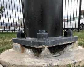
Dry-pack grouts, where grout is mixed to a putty-like consistency and packed around the perimeter of the connection, are susceptible to errors that could lead to incomplete filling of the space between the plate and the concrete. There is also a risk of incomplete mixing. Such conditions could lead to cracking, voids, degradation, inconsistent/low grout strength, and uneven stress transfer between the steel plate and the grout. Cracking and voids allow moisture to enter and pool, which can lead to accelerated corrosion and degradation of the connection, even in comparison to an ungrouted connection. An example of a poorly installed dry-packed grout pad is given in Figure 1, where the surface-only packing has led to corrosion and deterioration. With dry packing, a high degree of care in mixing, placement of adequate material to fill the void space, consolidation through vibration or tamping, and verification that the entire space has been filled are all essential. For these reasons, dry packing is recommended only if you can ensure the quality of installation meets engineering requirements.
Figure 1.
Poorly installed dry-packed grout pad Flowable, non-shrink grout enclosed within formwork is often employed to completely fill the void space between the steel plate and the concrete. Nevertheless, proper proportioning, mixing, and installation practices are still important for the proper functioning of the grout pad. Without proper placement, it is possible for air to become entrapped at the interface between the grout pad and the steel plate, which can be a possible location for water ingress and pooling that may lead to durability issues and uneven 3 / 18 stress transfer between the steel plate and the grout. Care should be taken to avoid air entrapment caused by, for example, vibration, well-placed air escape holes and formwork placement. Figure 2 shows proper installation for two types of base plate connection, where a flowable grout is set inside a confined region and allowed to completely fill the intended void space.
Figure 2. Installation of flowable grout for equipment support (left) and recessed column base (right)
For more information on structural grouting practices and the potential consequences of improper grouting or grouting out of sequence, see this article by Mullins and Parker [8] from STRUCTURE
magazine.
1.2 Structural behavior
1.2.1 Steel resistance of anchors in grouted connections
Steel resistance of anchors in grouted connections has been studied by a number of authors, including Adihardjo and Soltis [2], Nakashima [9], Gresnigt et al. [6], Gomez et al. [5], Fichtner [4], and McBride [7]. McBride [7] provides a summary of these research studies as well as behavioral explanations. Shear force transfer in grouted stand-off connections is complex, involving mechanisms of direct shear resistance of the anchors as well as friction due to compression forces acting on the connection. As the connection displaces in shear, cohesion at the plate/grout and grout/concrete interfaces is quickly overcome, leading to sliding along the respective planes and engagement of the anchor steel in dowel action. The deformed anchors are restrained from downward displacement and impose clamping forces on the connection that adds to the external compression forces. Figure 3 illustrates idealized force transfer mechanisms.
Figure 3. Idealized displaced shape of anchor in grouted stand-off connection (left). View of forces acting on free body of displaced
anchor (right) In addition, as the connection deforms in shear, struts form between anchors, causing cracking when the tensile strength of the grout is overcome. Figure 4 shows the cracking and crushing patterns from combined shear and moment on a grout pad from McBride [7].
Figure 4. Cracking behavior of grout pads under shear and moment loading: profile view (left) and plan view (right).
Compressive forces are shared between the grout pad and by anchors or shim stacks, as applicable. However, when grout pad tensile strength is exceeded by design forces, a reduced footprint of grout pad should be used for considering compressive resistance. This reduced footprint should consider the loss of grout outside the bolt line and should also consider a 45-degree cutaway from the compressive toe of the overturning moment on the connection. This translates to subtracting one grout pad thickness from the sides of the grout pad where bending is present as shown in Figure 5. For the purposes of section design, caution should be exercised when the thickness of the grout pad, 𝑡𝑔𝑟𝑜𝑢𝑡, exceeds the distance from the edge of the steel plate to the centerline of the anchors in a grouted stand-off connection. Caution should also be exercised when the cracking strength of the grout pad is exceeded due to shear forces on the connection. It is therefore recommended as a default assumption to distribute overturning moments on the connection only to the area enclosed by anchors in a grouted stand-off connection. This should be done unless it can either be verified that design loads will not cause grout pad cracking or that active measures are made to confine the grout pad (e.g., enclosing the grout pad in an FRP wrap).
Figure 5. Crushing due to the compression toe of bending moment acting on a grout pad.
Tensile forces are taken directly by anchors in stand-off connections when the lift-off load from pretensioning and clamping forces are overcome. It can conservatively be assumed that all tension loads
travel directly into anchors.
The interaction between shear and tensile forces in grouted connections involves all the mechanisms described above. However, McBride [7] found that the ACI 318 [1] provisions for steel resistance in grouted connections (described in Section 2.1.2 below) are adequate for describing steel resistance. Similarly, EN 1992-4 [3] provides equations for steel resistance of anchors in grouted connections based on the work of Fichtner (2012).
1.2.2 Concrete resistance of anchors in stand-off connections
Concrete breakout resistance in tension is assumed to be unaffected in grouted stand-off conditions. Concrete breakout forces in shear, however, may be amplified by the displacement of the anchor and by additional moment traveling through the connection. These factors should be considered for both ungrouted and grouted connections, resulting in the reduction factor given in Eq. (4). See the
accompanying article on ungrouted connections for more details.
2. DESIGN METHODS
Hilti PROFIS Engineering offers two solutions for the design of anchors in grouted stand-off connections: design compliance with Eurocode EN 1992-4 [3] and the Hilti Solutions for Fastenings (SOFA) Method. The EN 1992-4 approach generally provides conservative solutions to design. The Hilti SOFA Method provides state-of-the-art solutions that are less conservative and restrictive than the Eurocode. The primary differences between Eurocode design in accordance with EN 1992-4 design and Hilti SOFA Method are as follows:

2.1 Load distribution
For the purposes of bearing and bending resistance of the grout section, PROFIS Engineering removes the perimeter area encompassed by the centroid of the bolt line to account for the compressive struts between anchors. This assumption is illustrated in Figure 7. It follows that for single anchors or anchors arranged in a single row, no area will be enclosed by the bolt line, resulting in no usable grout area. In these cases, PROFIS Engineering conservatively assumes that the grout does not contribute to resistance and performs the bolt bending checks described in the accompanying ungrouted stand-off connection paper. Furthermore, if the thickness of the grout pad exceeds the distance from the centerline of any anchor to the edge of the base plate, PROFIS Engineering suggests to the user that bending of the anchors be considered due to the possibility of 45-degree crushing below the compressive toe of bending moments extending inside the bolt line. If user analysis determines that the full grout section can be used (e.g., after assessment that cracking and crushing will not occur), PROFIS Engineering will allow the full section of the grout pad to be used for section analysis.
Figure 7. Default assumptions about loss of section due to cracking and crushing for analysis of cross-section forces
2.2 EN 1992-4 Design
2.2.1 Axial steel resistance
Axial steel design resistance, 𝑁𝑅𝑘,𝑠, is determined in accordance with EN 1992-4 Section 7.2.1.3.
2.2.2 Steel shear resistance
In EN 1992-4 [3] provisions, the steel resistance of anchors with lever arm considers the failure by bolt bending, given in EN1992-4, Eq. 7.37. The bolt bending equations are given in the companion article for ungrouted stand-off connections.
In certain cases, considering the limitations from EN 1992-4, 6.2.2.3 (2), Eq. 7.36 as shown in Eq. (1) is used.
- At least two fasteners spaced at least 10𝑑 apart resist shear in the direction(s) of shear force.
- There is no bending moment or net tension on the connection.
- The grout thickness is no greater than the minimum of 40 𝑚𝑚 and 5𝑑 (5𝑑𝑜 for sleeve anchors).
- The grout pad completely fills the void space between the steel plate and the concrete.
- The compressive strength of the grout pad is as strong or stronger than the concrete and not less than 30 N/mm2.
When following PROFIS Engineering’s additional SOFA Method design considerations in 2.2 and 2.3, the bending moment limitation (item 2. above) may be relaxed in accordance with PROFIS Engineering’s design procedure.
𝑉𝑅𝑘,𝑠 = (1 – 0,01 ∙ 𝑡𝑔𝑟𝑜𝑢𝑡 ) ∙ 𝑘7 ∙ 𝑉𝑅𝑘,𝑠0 (1)
where
𝑡𝑔𝑟𝑜𝑢𝑡 = thickness of grout pad, mm
𝑘7 = ductility factor in accordance with EN 1992-4, 7.2.2.3.1 (2)
𝑉𝑅𝑘,𝑠 0 = characteristic steel shear resistance of anchor in accordance with EN 1992-4 Section 7.2.2.3.1
(1), Eq. (7.36).
2.2.3 Interaction of shear and axial forces for steel failure
When designing for bending using EN 1992-4 Eq. (7.37), the interaction of shear and axial forces is satisfied directly and is represented as a linear relationship between bending and axial force.
By definition, any anchors in tension will make EN 1992-4 design with Eq. (1) invalid.
2.2.4 Concrete failure modes in tension
Tensile concrete failure modes described in EN 1992-4, 7.2.1 (cone, pull-out, combined pull-out and concrete, concrete splitting, and concrete blow-out failure) are determined for grouted stand-off
connections in the same manner as for other connections without modification. Because Eq. (1) can only be used when there is no moment or tension on the connection, these provisions are only applicable to EN 1992-4 design when bolt bending is considered.
2.2.5 Concrete failure modes in shear
Shear pryout capacity of grouted stand-off connections remains identical to that in EN 1992-4 Section 7.2.2.4 whether Eq. (7.36) or Eq. (7.37) are used for anchor steel shear capacity.
However, when designing for bending using EN 1992-4 Eq. (7.37), design is restricted to a minimum edge distance of the larger of 10ℎ𝑒𝑓 and 60𝑑 in accordance with EN 1992-4 Section 7.2.2.5. For edge distances larger than this value, shear breakout resistance is not required to be calculated. Where closer edge distances are needed, the EN 1992-4 does not offer a solution and it is recommended to use the Hilti SOFA Method.
2.2.6 Interaction of shear and axial forces for concrete failure
Interaction between tension and shear concrete failure modes per EN 1992-4 Table 7.3 and shall satisfy either Eq. (7.55) or Eq. (7.56). Where supplementary reinforcement is present, EN 1992-4 Section 7.2.3.2 applies.
2.3 Hilti SOFA Method Design
2.3.1 Axial steel resistance
Axial steel design resistance, 𝑁𝑅𝑘,𝑠, is determined in accordance with EN 1992-4 Section 7.2.1.3.
2.3.2 Steel shear resistance
In ACI 318, 17.7.1.2.1[1], the steel shear resistance of anchors in grouted stand-off connections may be taken as 80% of the nominal shear steel resistance of the anchor. The Hilti SOFA Method adopts this design resistance. For the purposes of European design, variables have been translated to European terms and the 𝑘7 has been incorporated as shown in Eq. (2). For continuity, PROFIS Engineering has maintained limitations 1., 4., and 5. from Section 2.2.2 of this document, but has relaxed limitations 2. and 3. for grout pads up to 100 mm thick.
𝑉𝑅𝑘,𝑠,𝑔𝑟𝑜𝑢𝑡 = 0.8 ∙ 𝑘7 ∙ 𝑉𝑅𝑘,𝑠0 (2)
2.3.3 Interaction of shear and axial forces for steel failure
After converting 𝑉𝑅𝑘,𝑠,𝑔𝑟𝑜𝑢𝑡 and 𝑁𝑅𝑘,𝑠 to design values 𝑉𝑅𝑑,𝑠,𝑔𝑟𝑜𝑢𝑡 and 𝑁𝑅𝑑,𝑠 in accordance with EN 1992-4,
Table 7.1, the interaction of shear and tensile forces for the steel failure mode is determined in
accordance with EN 1992-4, Table 7.3 as shown in Eq. (3). By definition, any anchors in tension will make
EN 1992-4 design with Eq. (1) invalid, so this equation is only applicable to Hilti SOFA Method design.
(𝑁𝐸𝑑/𝑁𝑅𝑑,𝑠)2+ (𝑉𝐸𝑑/𝑉𝑅𝑑,𝑠,𝑔𝑟𝑜𝑢𝑡)2≤ 1.0 (3)
2.3.4 Concrete failure modes in tension
Tensile concrete failure modes described in EN 1992-4 7.2.1 (cone, pull-out, combined pull-out and concrete, concrete splitting, and concrete blow-out failure) are determined for grouted stand-off
connections in the same manner as for other connections without modification.
2.3.5 Concrete failure modes in shear
Shear pryout capacity of grouted stand-off connections remains identical to that in EN 1992-4 Section 7.2.2.4.
Shear breakout resistances of ungrouted stand-off connections remain identical to those in EN 1992-4, 7.2.2.5 with the multiplier 𝜓𝑏,𝑔 as given in Eq. (5) on the resistances in EN 1992-4 Eq. (7.40) to account for the bending forces transmitted through the anchor bolt to the concrete.
𝜓𝑏,𝑔 = 1/(1 +(𝐶𝑡𝑔𝑟𝑜𝑢𝑡/𝑑3/4)) (4)
where
𝐶 = a constant representing the elastic interaction between the anchor and concrete
= 0.043 for grouted connections and carries units of 1/𝑚𝑚0.25
2.3.6 Interaction of shear and axial forces for concrete failure
Interaction between tension and shear concrete failure modes per EN 1992-4 Table 7.3 and shall satisfy either Eq. (7.55) or Eq. (7.56). Where supplementary reinforcement is present, EN 1992-4 Section 7.2.3.2 applies.
For part 2 of this article follow this link
You are also welcome to ask us for support: simply leave a comment or post your question in the community, or improve your knowledge and skills via our Webinars or training sessions.
For the latest news in engineering solutions and innovations follow us on: LinkedIn, Instagram and Twitter
