
Design of the longitudinal Shear Strength of Concrete-to-concrete Interfaces acc. to EOTA TR06
The current European standard for the design of reinforced concrete structures EN 1992-1-1 (EC2) [1] contains rules for the design of the shear capacity of concrete/concrete joints of semi-precast concrete elements. However, for the design of reinforced interface with post-installed shear connectors EOTA TR 066 [2] is the appropriate design approach.
This article takes a comprehensive look at the topic of concrete overlay. It examines the current dimensioning regulation for overlay and deals with the individual load-bearing components that describe the load-bearing resistance of the interface of concrete overlay. In addition, information is given on the preparation of the interface surface and installation of the post-installed shear connectors on the basis of EOTA TR 066 [2]. Finally, solutions are shown how a design can be modelled and calculated as a whole. Here we refer to the concrete overlay module of the Hilti design software PROFIS Engineering.
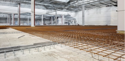
Figure 1 A typical application of concrete overlay in civil engineering is the reinforcement or renovation of industrial flooring
The installation of new, retrofitted concrete layers (concrete overlay) is becoming increasingly important due to the growing need for repair and reinforcement of existing structures. Bridge cross-sections reinforced by a new concrete layer as well as the repair and reinforcement of existing concrete components by a new concrete layer are typical examples of the use of overlay, see Figure 2. If the shear stresses in the bonded joint between the concrete layers that were poured at different times are not sufficiently transferred, the structural safety is at risk.
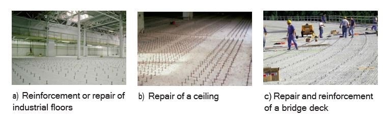
Figure 2 A typical application of concrete overlay in building construction and civil engineering
Figure 3a shows the stress state of a beam without the activation of shear stresses between the concrete layers (unreinforced interface). In this case, the concrete layers behave independently of each other. This is a simplification, because even in the case of an unreinforced interface, an adhesive bond acts between the concrete layers. However, the adhesive bond is already impaired at relative deformations of 0.03 mm to 0.05 mm due to cracking between the interface. In order to achieve a monolithic connection, post-installed shear connectors are usually placed. This allows, for example, bending compression and/or bending tension zones to be enlarged (structural reinforcement) or the original zone heights to be restored (refurbishment), see Figure 3b.
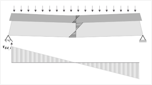 a) Without the activation of shear stress
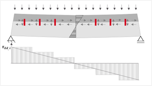 b) With the activation of shear stress
Figure 3 Beam without and with activation of shear stresses in the interface
The new design concept according to EOTA TR 066 "Connector for strengthening of existing concrete structures by concrete overlay" [2] allows the design and dimensioning of these connections and the interface taking into account all load-bearing components (cohesion/friction, interlocking and dowel action) and other product-specific factors.
Thus, EOTA TR 066 [2] reflects the current state of the art in the design of overlay applications with post-installed shear connectors. This contrasts with EN 1992-1-1 (EC2) [1], which does not take into account the individual load- bearing behavior of post-installed shear connectors. Figure 4 shows the "long way" from the design of post-installed shear connectors with the Hilti method (2001) to the general building inspectorate approvals (2010) to the "fib Model Code" 2010 [3] and finally the EOTA TR 066 [4] in 2019.
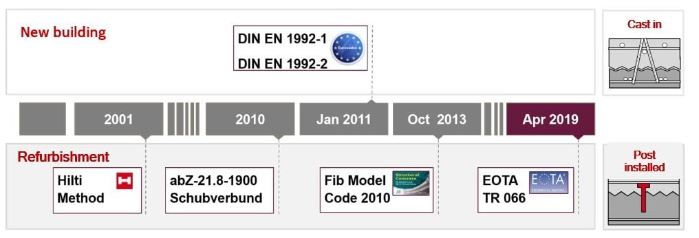
Figure 4 The "long way" of post-installed shear connectors to the final design according to EOTA TR 066 [2].
2 Implementation of concrete overlay application
The implementation of a construction measure with concrete overlay can be roughly simplified and divided into several work steps: The demolition or exposure of the existing, damaged concrete layer, the roughening of the surface, the installation of the post-installed shear connectors, the insertion of the new reinforcement and finally the placement of the new concrete layer (Fig. 5).
Before we describe the design approach of EOTA TR 066 [2], we provide some important advice on surface preparation and subsequent installation of shear connectors, as found in part in EOAT TR 066 [2].
Depending on the country, additional technical guidelines (e.g. ZTV-ING (Germany)), technical building regulations (e.g. EiT (EBA, Germany), technical manuals (e.g. Tunnel/ Geo-technik (Switzerland) or guidelines and regulations (e.g. RVS (Austria)) in conjunction with national guidelines and standards must be taken into account.

Figure 5 Simplified overview of the execution steps of a construction measure with overlay
2.1 Preparation of the surface and installation of the post-installed shear connectors-Roughening of the surface is usually carried out by high-pressure water jetting. Other methods than high-pressure water jetting are not permitted, referencing on local or additional guidelines. This derives for example of Micro-cracks which can occur during roughening by milling and lead to damage of the concrete structure. Exposed aggregates that are well anchored in the concrete must be clearly visible [2]. The required average roughness depth Rt must correspond to the specified minimum value.
The average roughness depth itself can be determined according to the Kaufmann sand surface method or by means of an electronic, optical measurement [2]. The principle suitability of the roughened old concrete is to be checked by measuring the bond strength perpendicular to the interface (adhesive tensile strength) fh, whereby at least the value of fh≥ min (1.5 N/mm²; fctm) must be achieved [2]. The scope of testing for the measurement of the roughness depth and the tensile strength shall be carried out in accordance with EOTA TR 066 [2], taking into account additional guidelines, building codes or regulations, whereby in particular for the measurement of the roughness depth the obviously least roughened areas shall be used.
2.1.1 Requirements for the cleanliness of the interface -The work sequence must be designed in such a way that the interface always remains clean from the time of roughening until the concrete is placed [2]. Tire abrasion and contamination of the surface must be avoided as far as possible. Special attention is be paid to the fact that the drilling dust must be extracted during the drilling process without exception [2]. If the surface is to be cleaned with compressed air, the air flow must be free of oil [2].
2.1.2 Post-treatment of the roughened surface-The clean interface must be kept moist for several days before placing the concrete. On the day of concreting, water puddles, regardless of their size, must be vacuumed [2]. At the time of concrete pouring, the surface must be slightly dry (silk matt) [2] to support the hydration of the fresh concrete in the area of the interface.
2.1.3 Post-installed shear connectors - There is a range of post-installed shear connectors available. A distinction can be made between concrete screw systems and mortar systems.
The installation of the shear connector type "concrete screw", e.g. Hilti HUS4, takes place in three steps. First, a hole is drilled in the existing concrete, ideally dust-free, using a hollow drill bit, e.g. Hilti Hollow Drill Bit. The standard hammer drilling method with corresponding ETA-compliant cleaning can also be carried out.
The ETA also describes installation situations where the borehole cleaning with Hilti shear connectors may be completely omitted. The concrete screw is driven in with a special impact screwdriver. The drilling depth is typically chosen slightly greater than the screw-in depth to create space for the dust and debris of the thread cutting process in the concrete.
The tensile load-bearing behavior of this system depends on the tolerance of the drilled hole, which is regulated in the ETA for the product. Due to the thread cut into the concrete, this shear connector is adjustable in height to a certain degree (Figure 6).
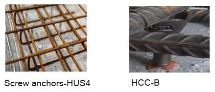
Figure 6 Installation of Hilti shear connectors with overlying reinforcement layer
The post-installed shear connectors of the "bonded anchor" type are special elements or standard elements equipped with additional accessories, e.g. HCC-B (special element, optimised for positioning the reinforcement and installation (Figure 6)). Regardless of the element, a borehole is drilled in the existing concrete and the drilling dust must be removed during drilling as described above. Therefore, Hilti offers the SAFEset technology, in which the dust is automatically extracted during the drilling process and the drill hole is additionally cleaned in compliance with ETA. The mortar is injected into the borehole with an automatic or pneumatic dispenser before the element is inserted into the borehole. Figure 7 provides an overview of the various Hilti shear connectors and their technical properties and range of applications.
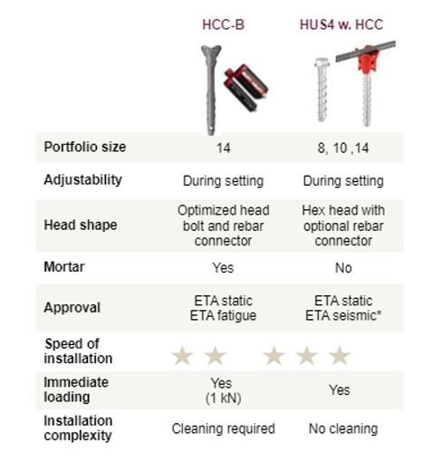
Figure 7 Overview of Hilti shear connectors HCC (Hilti Concrete Connector) and their technical properties for the design of the shear capacity of interface according to EOTA TR 066 [2].
3 Load-bearing behavior of the interface
The behavior of interface subjected to longitudinal shear stresses can be described using the shear-friction theory. It should be noted, however, that the term "shear-friction theory" may be misleading as it includes several different stages of development. The original "shear-friction theory" assumes that the transmission mechanism of shear stresses in an interface that is simultaneously subjected to shear and compression forces is only ensured by friction. Generally, a simple sawtooth model is used to illustrate the basic principles of this theory (Figure 8).

Figure 8 "Shear-friction theory" as sawtooth model 1960 by Birkeland and Birkeland [5].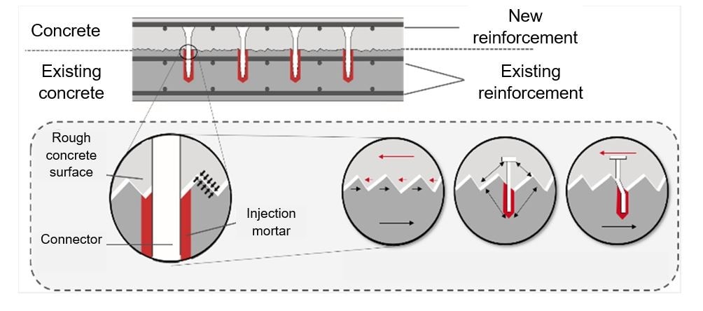
Figure 9 Shear transfer in the reinforced composite joint: cohesion / interlocking, friction and dowel effect using the example of the shear connector HCC-B.
This theory was developed around 1960 by Birkeland and Birkeland [5]. In 1972, it was extended by Mattock and Hawkins [6] to include the load-bearing component of cohesion. In 1978, concrete compressive strength was included in the theory as proposed by Loov [7]. Finally, Randl [8] describes that the shear transfer in the reinforced composite joint consists of three main mechanisms: cohesion, friction and dowel action. The three main mechanisms can be clearly described in Figure 9. Figure 10 shows the shear stress curve as a function of the relative displacement of the individual load-bearing mechanisms (adhesion/interlock tadh, friction tsf and shear reinforcement tsr (Zilch and Reinecke [9]). The adhesion component tadh results from chemical adhesive bonds between the particles of the old and new concrete.
When the maximum load-bearing capacity of the adhesive bond is reached, detachment occurs at the interface between the concrete layers and the shear stresses are transferred by mechanical interlocking due to surface roughness. As the relative displacement between the concrete layers increases, the shear connectors crossing the interface are stressed and the shear connectors may fail by yielding of the steel, pullout failure or other possible failure modes. As a result of the resistance of the shear connectors, the interface is subjected to compression and the shear forces are transmitted by friction (tsf). Due to the relative displacement of the concrete layers, the post-installed shear connector is also subjected to shear force, which is usually referred to as dowel action (tsr).
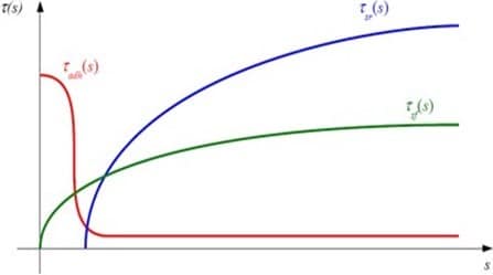
Figure 10 Shear stress curve as a function of relative displacement for the individual load-bearing mechanisms (adhesion/interlock tadh, friction tsf and shear reinforcement tsr (dowel action) (Zilch and Reinecke [9]).
With increasing surface roughness, the shear resistance and the shear stiffness of the composite joint increase considerably. In addition, the distribution of the total resistance between the three load-bearing components changes. In the extreme case, when the interface is very rough, the connectors at the joint are mainly subjected to tensile stress, whereas with a smooth interface the dowel stress on the connectors in shear is predominant.
This article continues, read part 2 of this article to learn more.
Authors

You are also welcome to ask us for support: simply leave a comment or post your question in the community, or improve your knowledge and skills via our Webinars or training sessions.
For the latest news in engineering solutions and innovations follow us on: LinkedIn, Instagram and Twitter
This article is part of an ongoing series dedicated to Rebar topics. Find more here
