
What is the HIT-Glass method?
1. WHAT IS HIT-GLASS METHOD?
Glass balustrades are very common in residential and commercial structures. Typical construction methods include a glass pane that rests in a “U-profile” (typically made from steel or aluminum) that is secured to the structural base material. Generally, the U-profile is wider than the glass pane allowing for installation flexibility. After the glass is inserted into the U-profile, a solid filler is used to embed the glass pane in the U-profile.
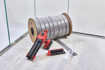
Fig. 1.1: Hit-glass method accessories
See below (Fig. 1.2) item 3, for typical filler location. Traditionally, poured-in grouts are used as a solid filler; however, they are often difficult to install due to the extensive preparation required for the U-profile, as well as the manual process of mixing and pouring the grout. In addition, transporting the grout to the site and the relevant floors is complex and time-consuming. Hilti proposes the HIT-Glass solution which relies on the high-performance HIT-HY 270 mortar as the preferred filler solution for embedding the glass panes in the U-profile.
Fig. 1.2: Typical cross section of glass balustrade with HIT-HY 270 filler material
Traditional installation of HIT-HY 270 for glass balustrades follows the “Line Method” consisting of a continuous strip of mortar at the top and bottom of the U-profile on each side of the glass. Hilti has recently performed testing apply a smaller amount of mortar in the form of U shaped “pucks” spaced a maximum of 457 mm apart, called the HIT-Glass Method. See below (Fig. 1.3).
Fig. 1.3: Side view of glass pane, U-profile and Hit-Glass method with HIT-HY 270
By injecting and curing HIT-HY 270 mortar between the glass pane and the interior of the U-profile, the cured “pucks” create a hardened material that acts as a compression block for loads acting perpendicular to the glass pane assembly. HIT-HY 270 does not bond with the U-profile or glass and thus does not provide resistance against in-plane motion (i.e., vertical or parallel directions). A top rail or top cap is generally used in 2 / 8 conjunction with a structural sealant to resist vertical uplift. However, a top rail or top cap is not required provided that the installer takes additional measures to ensure that the uplift of the glass panes will not occur in all installation types (inclined, and/or level), and that sliding of the glass panes will not occur in vertically inclined installations.
2. WHY SHOULD WE CONSIDER USING HIT-GLASS METHOD FOR GLASS BALUSTARDE APPLICATION INSTEAD OF ALTERNATIVE SOLUTIONS?
The HIT-Glass method offers a variety of advantages for the design, installation, and maintenance of glass balustrades. In design, HIT-HY 270 is durable and has been tested according to recognized industry standards, including ASTM E935, ASTM E2353, ASTM E2358, A500-16 and BS 6180. [1] For installers, injection of the mortar is made simpler and cleaner with the dispensing Nozzle HIT-RE 60-Glass mixer attachment for precision placement and a mortar viscosity resistant to dripping, even in applications with inclines up to 35 degrees. [2] Our Insert HIT-Glass EP 9.5 foam and Insert HIT-Glass EP 13 foam rolls provide a continuous profile of material with an adhesive strip on one side that is cut to length by the installer according to the geometry of the installation. These positioning aids are placed on the bottom of each glass pane in a U-shape on either side of each HIT-HY 270 injection location. The positioning aids allow for injections to take place from the protected side of the balustrade, providing a faster, safer, and simpler installation. This is possible because the gap created by the aids lets the mortar pass beneath the glass pane and up the other side of the U-profile. In addition, the aids offer easier glass adjustability over mechanical wedge systems in curved glass applications. For the long-term maintenance of the balustrade assembly, individual glass panes can be removed and replaced with ease because HIT-HY 270 does not bond to the glass or the U-profile. The installer can easily replace both the damaged glass pane and the required mortar pucks during repair operations. You can watch the HIT-Glass installation how-to video by using the HIT-Glass Instructions for Use (IFU) which is linked below. Once you click the link you can use the QR code on the document.
IFU HIT-Glass
3. CALCULATION METHODOLGY FOR MINIMUM REQUIRED PUCKS TO MEET LOAD DEMAND
As mentioned, you must install pucks to a certain size and a minimum number of pucks per glass pane with maximum spacing. The following calculation methodology can be used to determine the number of pucks for a specific glass pane and applied load.
The wind and live load will be determined by the project Engineer of Record (EOR) and need to be less than design input of boundary conditions. The calculation method below is only evaluating the loads on the HIT-HY 270 mortar and the EOR is responsible for the design of the balustrade, supporting structure, and glass panes; EOR will need to verify the HIT-HY 270 solution, calculation, and placement is applicable for the project specifications and design codes.
For straight and level glass balustrade designs installed according to the HIT-Glass method in rectangular U-profile Hilti has launched a new module in PROFIS Engineering called “Glass Balustrade” to give more peace of mind that glass balustrade specifications will be installed correctly. The module allows the user to enter the balustrade geometry and a service wind and live load for the design. The HIT-Glass Design Report generated by the module provides project inputs, design calculations, output results, options for Bill of Materials, and HIT-Glass Instructions for Use (IFU).
Visit www.profisengineering.hilti.com for more information.
3.1 Calculation assumptions
This calculation methodology is applicable for glass balustrade designs that are:
• Straight and level
• Installed in U-shaped profile with rectangular geometry
• Installed according to the Hilti HIT-Glass method
For V-shaped profiles, curved and/or inclined applications, and all applications that fall outside of the boundary conditions supported by the HIT-Glass Method, the EOR may refer to the below calculation methodology for adaptation according to the loading distribution and geometry requirements of the design.
Live and wind load (WL, LL) acts orthogonally and uniformly at the top and across entire of the glass pane.[3] See below. (Fig. 3.1) The compressive stress on the pucks does not act uniformly. Instead, the greatest stresses are seen at either the top or bottom of the puck and gradually decrease to a stress of 0 in a triangular loading pattern. (Fig. 3.2) below for a load diagram which is assumed by Hilti as the forces acting on the system. The EOR should verify that this load diagram is applicable for the actual application.
Fig. 3.1: Theoretical free body diagram Fig. 3.2: Stress distribution within the U-profile
Table 3.1: Calculation required variables for a project
When using the HIT-Glass method, each puck width is required to be 60 mm, which is the width of the Nozzle HIT-RE 60-Glass mixer attachment used for injections. It is also the same width as the Insert HIT-Glass EP 9.5 foam and Insert HIT-Glass EP 13 foam used as positioning aids during installation. 𝑤𝑝𝑢𝑐𝑘 = 𝑤𝑝𝑜𝑠𝑖𝑡𝑖𝑜𝑛𝑖𝑛𝑔 𝑎𝑖𝑑 = 60 𝑚𝑚 Each effective puck height is equal to the interior U-profile height reduced by 5mm for a strip of structural sealant to be placed at the top of the U-profile and the thickness of the gap between the glass pane and the bottom of the U-profile, since the mortar beneath the glass pane will not resist any lateral loads.
Fig. 3.3: Section view of glass pane, U-profile
The long-term characteristic compressive strengths of HIT-HY 270 based on service temperature range are shown Table in 3.2. These values have been experimentally derived by an independent expert [1]. 
Table 3.2: HIT-HY 270 the long-term characteristic compressive strength
A safety factor of 2.5 has been applied in the calculations, in line with Hilti’s recommendation.[1] The resulting allowable compressive strength 𝐶𝑎 is calculated as shown below:
3.2 Design steps
Step 1: Actions should be calculated in accordance with EN-1991-1-1 or, where applicable, the corresponding national regulations. [4] Step 2: Calculate design live, wind load and combined shear loading
This equation is a result of calculation of stress based on Figure 3.1 above in order not to exceed the allowable compressive strength of the HIT-HY 270 mortar material. The EOR will ultimately determine the validity of this analysis. The greatest value of 𝒙𝒅𝒆𝒎𝒂𝒏𝒅 controls the design for load demand.
Step 5: Determine governing number of pucks required per glass pane as the greatest of the three requirements below
At least 3 pucks required per pane regardless of length, 𝒙 = 𝟑
Pucks are spaced no further apart than 457mm in the centre,
Required number of 60mm pucks to resist demand, 𝒙 = 𝒙𝒅𝒆𝒎𝒂𝒏𝒅
3.3 Calculation methodology for volume of mortar required
The following approximates the amount of HIT-HY 270 mortar an installer would need to fill in the U-profile with the number of pucks calculated above. This calculation methodology includes an assumed %17 waste for 330 ml cartridges and an assumed %12 waste for 500 ml cartridges due to the losses in the dispenser and accessory attachment. This is only approximation, and the amount could vary from actual job-site conditions.
Per the HIT-Glass Instructions for Use (IFU), an amount of mortar is to be discarded to ensure proper ratio of hardener to resin before injection.
Thus, 330 ml/cm3 and 500 ml/cm3 cartridges have effective volume of:
Once the number of pucks per pane has been determined, calculate the number of tubes by determining the amount of volume required for the project divided by the effective volume of the desired tube size. Total number of pucks per pane = 𝒙 Total number of panes = n
4. CONCLUSION
In conclusion, the Hilti HIT-Glass system provides a reliable and innovative solution for glass balustrade installations. By combining high-performance chemical anchoring with purpose-designed tools, it ensures durability, safety, and aesthetic excellence in the projects. This system not only simplifies installation but also enhances long-term performance, making it an essential choice for engineers, contractors, and architects aiming to meet both structural and design requirements. To start designing, visit https://profisengineering.hilti.com/
REFERENCES
[1] C. Schuler, and J. Grötzner, Expert Opinion on the Use of Hilti HIT-HY 270 for the Support of Balustrades and Balustrade System Made of Glass, Karlsruhe: Engineering office for structural engineering, 2025.
[2] IFU Hit Glass: Instructions for Use Hit Glass, Schaan: Hilti Corporation, 2025.
[3] Technical Design Specification: Hit Glass Design Method Specification, Schaan: Hilti Corporation, 2025
[4] EN 1991-1:2002: Eurocode 1 - Actions on structures - Part 1: General actions - Densities, self weight, imposed loads for building, Brussels: CEN, 2002.
